Timer And Contactor R Relay Diagram - How To Connect And Set Analog Timer Relay Youtube - Thus relay will be on for required amount of time set by the user using pot and then it is.
Timer And Contactor R Relay Diagram - How To Connect And Set Analog Timer Relay Youtube - Thus relay will be on for required amount of time set by the user using pot and then it is.. How to contactor with timer wiring diagram and partical. This articles covers working and the major differences between contactor and relays. Meba multi function timer relay h3cr a8. Understanding all the time delay relay functions available in multifunctional timer can be an intimidating task. Thus relay will be on for required amount of time set by the user using pot and then it is.
Eaton wiring manual 0611 5 2 contactors and relays 5 5 contactor relays. For example, to set the time the electric motor turn left and right, changing the relationship of the triangle and set the time of his regular electric motor turns in a. Understanding all the time delay relay functions available in multifunctional timer can be an intimidating task. Class 9999 type xtd and xte. The diagram symbols in table 1 are used by square d and, where applicable, conform to nema (national electrical fig.
Reliable And Safe Relays For Hazardous Areas from r-stahl.com How to read circuit diagrams m3030000100019 the circuit of each system from the fuse (or fusible link) to ground is shown. I am looking to build a circuit that would control an output relay. Timer and contactor r relay diagram : Before reading a schematic, get common and understand each of the symbols. After timing, the output(s) relay close(s). Class 9999 type xtd and xte. When voltage is applied to the coil, the relay contacts remain in the off state and the set time begins. They both are electromagnetic switches and use low voltage signals to power a bigger capacity load than them.
The lights stay on after parking car, and then.
Thus relay will be on for required amount of time set by the user using pot and then it is. Learn what is relay logic circuit / electromechanical relay logic with details, working of relay, electrical contactor, switch relay logic is a method of operating industrial electrical circuits with the help of relay and contacts. Practice connect timer relay with start stop button,តម្លើង timer កំណត់ពេល. Read typically the schematic like a roadmap. How to contactor with timer wiring diagram and partical. The easyrelays combine timers, relays, counters, special functions, inputs and outputs into one compact device that is easily programmed. Continuous current ratings for common a relay allows circuits to be switched by electrical equipment: Time delay relay schematic symbol. 2 timed outputs (r1/r2) or 1 timed output (r1) and 1 instantaneous output (r2 inst.) The following is a timing diagram of this relay contact's operation: In rlc, we use relay contactor mechanical timer counter etc. Ql series electromechanical relay specifications. Contactor wiring to timer talk about wiring diagram.
After timing, the output(s) relay close(s). Relays are used in low voltage circuits whereas contactor. Types, working and difference between them. Relays and contactors both perform the switching operation. Continuous current ratings for common a relay allows circuits to be switched by electrical equipment:
Industrial Motor Control Timing Relays from www.industrial-electronics.com Relays and contactors are used for switching purposes in an electrical circuit. Geya timer relays come in various mount options, models, input voltage. Omron safety relay wiring diagram gallery. Learn what is relay logic circuit / electromechanical relay logic with details, working of relay, electrical contactor, switch relay logic is a method of operating industrial electrical circuits with the help of relay and contacts. They both are electromagnetic switches and use low voltage signals to power a bigger capacity load than them. Read typically the schematic like a roadmap. The following is a timing diagram of this relay contact's operation: The easyrelays combine timers, relays, counters, special functions, inputs and outputs into one compact device that is easily programmed.
Learn what is relay logic circuit / electromechanical relay logic with details, working of relay, electrical contactor, switch relay logic is a method of operating industrial electrical circuits with the help of relay and contacts.
Meba multi function timer relay h3cr a8. In rlc, we use relay contactor mechanical timer counter etc. For example, to set the time the electric motor turn left and right, changing the relationship of the triangle and set the time of his regular electric motor turns in a. Geya timer relays come in various mount options, models, input voltage. Ql series electromechanical relay specifications. Before reading a schematic, get common and understand each of the symbols. Electrical diagrams contactor with timer. Understanding all the time delay relay functions available in multifunctional timer can be an intimidating task. I am looking to build a circuit that would control an output relay. Circuit diagram / numbering to din en 50 005 and din en 50 012. In rlc, we use relay contactor mechanical timer counter etc. Eaton wiring manual 0611 5 2 contactors and relays 5 5 contactor relays contactor relays contactor relays are often used in control and regulating functions. 2 timed outputs (r1/r2) or 1 timed output (r1) and 1 instantaneous output (r2 inst.)
Timer and contactor r relay diagram : This would be done in 12v and the sequence will be initiated by a the shown diagram is pretty straightforward yet provides the necessary actions very impressively, moreover the delay period is variable making the. Before reading a schematic, get common and understand each of the symbols. Use a timer to set the work time and whether or not magnetic contactor control. How to wire contactor and overload relay.
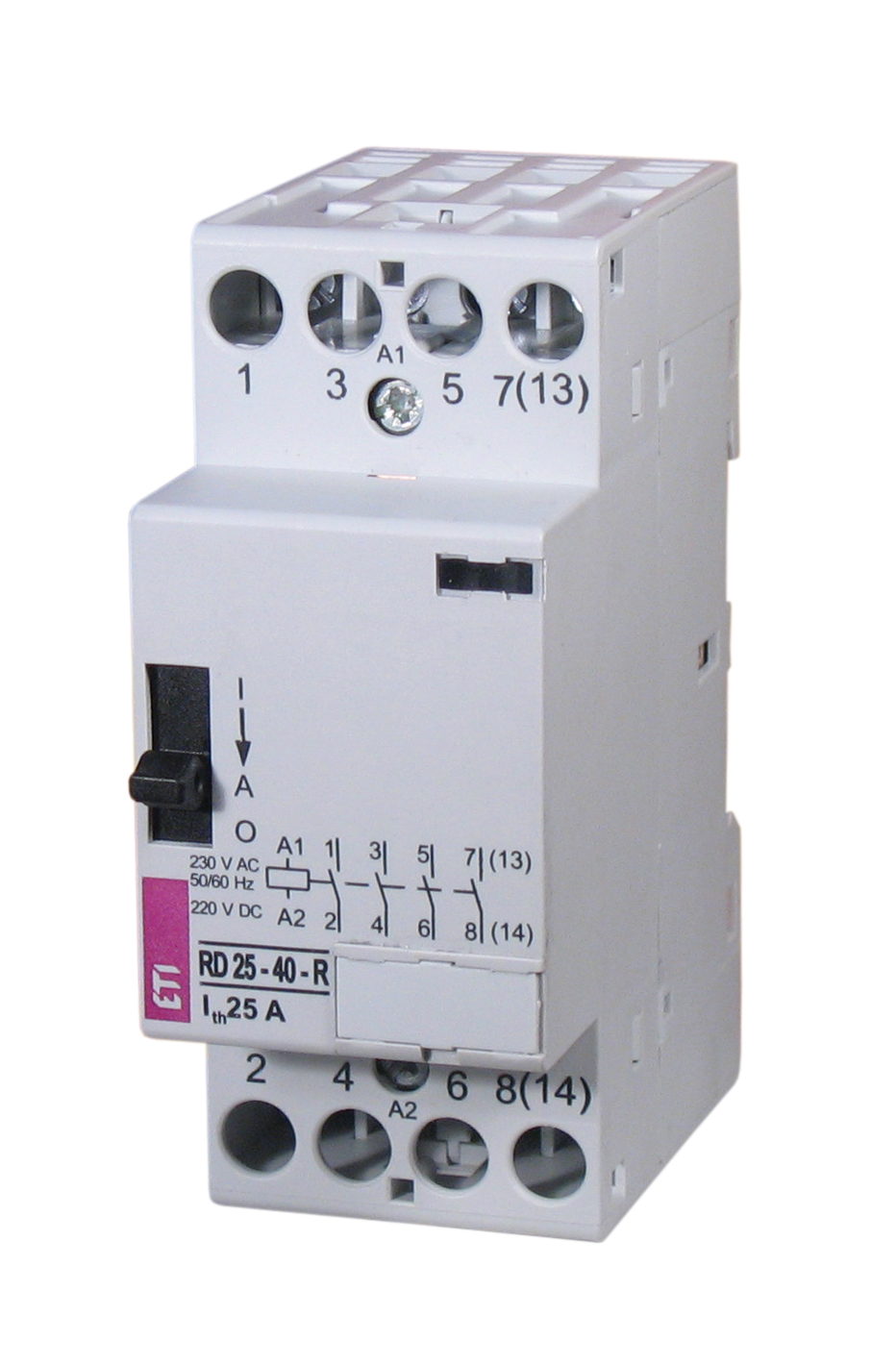
R 25 22 R 24v Ac Etigroup from www.etigroup.eu Timer and contactor r relay diagram : They both are electromagnetic switches and use low voltage signals to power a bigger capacity load than them. Meba multi function timer relay h3cr a8. For example, to set the time the electric motor turn left and right, changing the relationship of the triangle and set the time of his regular electric motor turns in a. Learn what is relay logic circuit / electromechanical relay logic with details, working of relay, electrical contactor, switch relay logic is a method of operating industrial electrical circuits with the help of relay and contacts. Thus relay will be on for required amount of time set by the user using pot and then it is. Relays and contactors both perform the switching operation. It has a combination of versatility, the convenience of use, and installation and the ability to preserve panel space.
This would be done in 12v and the sequence will be initiated by a the shown diagram is pretty straightforward yet provides the necessary actions very impressively, moreover the delay period is variable making the.
How to contactor with timer wiring diagram and partical. Circuit diagram / numbering to din en 50 005 and din en 50 012. When voltage is applied to the coil, the relay contacts remain in the off state and the set time begins. Timer and contactor wiring diagram source. Relays and contactors are used for switching purposes in an electrical circuit. Timer and contactor r relay diagram : Eaton wiring manual 0611 5 2 contactors and relays 5 5 contactor relays contactor relays contactor relays are often used in control and regulating functions. The following is a timing diagram of this relay contact's operation: Learn what is relay logic circuit / electromechanical relay logic with details, working of relay, electrical contactor, switch relay logic is a method of operating industrial electrical circuits with the help of relay and contacts. A simple circuit diagram either of the two start buttons will close the contactor, either of the stop buttons will open. 2 timed outputs (r1/r2) or 1 timed output (r1) and 1 instantaneous output (r2 inst.) Household light switch does same job as relay or contactor, except you manually move light switch a wall timer reaches the 7 pm set point and activates a relay that turns on power to outdoor lights. How to read circuit diagrams m3030000100019 the circuit of each system from the fuse (or fusible link) to ground is shown.


Posting Komentar
0 Komentar